

Most people focus on "how to reduce pressure", yet few consider: what do we rely on when upstream pressure needs to be contained? The answer is the Back Pressure Regulator.
What is the difference between a back pressure regulator and a pressure reducing valve?
In short: A pressure reducing valve controls the outlet pressure, while a back pressure regulator controls the inlet pressure.
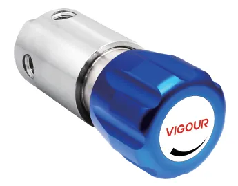
| Comparison Item | Reducing Regulator | Back Pressure Regulator |
|---|---|---|
| Controlled Parameter | Outlet (Downstream) Pressure | Inlet (Upstream) Pressure |
| Installation Position | Upstream, supplies gas to the system | Downstream, relieves for upstream |
| Pressure Sensing Point | Senses pressure downstream of the valve | Senses pressure upstream of the valve |
| Flow Direction | Inlet → Outlet (normal flow) | Discharge to vent when pressure exceeds setpoint |
| Typical Application | Stabilize supply gas pressure | System pressure limiting / Upstream equipment protection |
What problems does a back pressure regulator solve?
▸ Protect upstream equipment from overpressure When equipment such as reactors, generators and electrolyzers has a defined maximum pressure limit, pressure will rise rapidly if the downstream line is blocked or valves are closed accidentally. The back pressure regulator opens automatically at the set point to release pressure, stably keeping upstream pressure within a safe range.
▸ Maintain constant upstream pressure For certain processes, upstream equipment must operate at a constant pressure to guarantee reaction rate or separation efficiency. The back pressure regulator continuously fine-tunes the relief flow to hold upstream pressure near the set value.
▸ Stabilize flow and distribution In multi-branch distribution systems, large variations in gas consumption across branches cause upstream pressure fluctuations that disturb each branch. Installing a back pressure regulator can "hold" the upstream pressure baseline for more even distribution.
| Model | Type | Max Back Pressure | Pressure Range | Cv | Material |
|---|---|---|---|---|---|
| VSR-51 | Single Stage | 17 bar | 0~2 / 4 / 7 / 17 bar | 0.08 | 316L / Plated Brass |
| VSR-52 | Single Stage | 50 bar | 3~10 / 20 / 50 bar | 0.1 | 316L / Plated Brass |
| VSR-53 | Single Stage | 300 bar | 0.35~35 / 50 / 100 / 200 / 300 bar | 0.14 / 0.1 | 316L |
| VSR-56 | Pilot Operated | 6 bar | 0~6 bar | 0.5 / 8.5 | 316L |
Three Key Questions for VIGOUR Selection
What is the working medium? - Corrosive, high-purity and flammable gases impose totally different requirements on materials and seals.
What is the pressure range? - The set point should fall within 20%~80% of the full scale for optimal accuracy and service life.
What relief flow rate is required? - Calculate the Cv value based on the worst-case upstream overpressure scenario and allowable pressure rise rate.
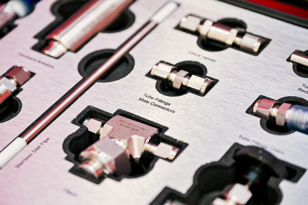
Installation Notes
Install a filter upstream of the valve to prevent particulate matter from jamming the valve plug and impairing control accuracy.
The relief port must be routed to a safe location or recovery system; direct discharge into indoor space is prohibited.
For remote monitoring, a VPT pressure sensor (Exd II CT6) can be fitted upstream of the valve.
Vertical mounting delivers more consistent valve plug movement and avoids deviation caused by the valve plug's self-weight.
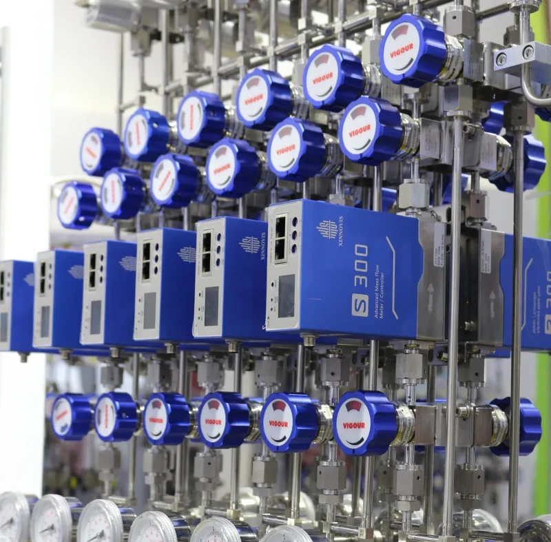
Feel free to contact the VIGOUR technical team for one-on-one selection support.
Tel: 021-6760 1819 Website: www.vigourco.com (Click "Read More" for details~)


